Teleradiography allows you to obtain a panoramic image of the skull in profile and front. The picture is taken at a distance of one and a half to two meters, so it is possible to obtain an image almost life-size.
Unlike intraoral X-rays, tele-X-rays show a more complete picture of the condition of the dental system, and therefore are considered the most informative method of X-ray diagnostics. Widely used by orthopedic dentists and recommended before performing maxillofacial surgeries.
What is TRG?
Teleradiography is an X-ray method for examining a patient, which is widely used among orthodontists, as well as surgeons and traumatologists.
The main feature of the photograph is its projection. It shows the entire skull in a frontal or lateral section. The doctor can obtain a large amount of information from a single TRG image.
For example, the specialist sees the skull as a whole, the relationship of the bones, the relationship of the jaws, the condition of the temporomandibular joint and occlusal relationships, as well as soft tissues. All these parameters are extremely important for choosing the right treatment tactics.
How much does such a procedure cost?
Different clinics have different prices for TRG. Basically they fluctuate in the range of 800 – 3900 rubles . This price difference is determined by the following factors:
- The location and prestige of the clinic where you are going to perform the procedure.
- Subscription and discounts for regular customers.
- Quality and equipment of equipment.
- The experience and qualifications of the specialist who will advise and treat you.
- Type of diagnosis.
Basically, the price of the study includes recording the image on disk and printing it.
Sources:
- https://stoma.guru/lechenie/kak-primenyaetsya-v-stomatologii-telerentgenogramma.html
- https://orto-info.ru/ortodonticheskoe-lechenie/podgotovitelnyiy-period/informativnost-telerentgenogrammyi.html
- https://zub.guru/specialisty-i-metody-diagnostiki/trg-v-bokovoy-proekcii-cherepa-primenenie-v-stomatologii.html
- https://smilestom.spb.ru/optg-trg-3d-snimok-kakoj-vid-diagnostiki-vam-nuzhen-09-02-2018-2479/
- https://Center-Luch.ru/stati/chto-takoe-trg/
- https://rodenmed.ru/pacientam/chto-takoe-telerentgenogramma/
- https://MyDentist.ru/diagnostika/telerentgenografiya/
- https://ionika-dent.ru/services/diagnosis/trg/
When is TRG performed?
Most often, a TRG image is needed at the planning stage of orthodontic treatment. Based on special calculations made, the doctor makes a decision on which treatment method is suitable in each specific case. In the image you can see many obvious and hidden pathologies, and based on the calculations, draw conclusions about the state of the dental system, determine the diagnosis and find out which treatment methods may be contraindicated in this case. TRG is often a mandatory and sometimes priority examination method for an orthodontic patient.
For a surgeon and traumatologist, such an examination can help detect trauma to the cranial bones and see the displacement of fragments due to the fact that the bones are visible in different projections. Timely identification of injury and its location can radically change treatment tactics and prevent complications.
What types of TRGs are there?
Depending on the case, the doctor may prescribe TRH in one of two projections. Only a specialist decides which image is needed, since it is based on the results obtained that he will be able to correctly make a diagnosis.
Types of TRG:
- In frontal projection. This image shows the front or back of the skull. The doctor sees the relationship of the facial bones, and may also notice the presence of inflammatory processes in the maxillary (maxillary) sinuses.
- Lateral projection. An image in this projection is often important for orthodontists. It shows all the points for calculations, the relationship of jaws and teeth and many other details. The image shows the skull bones and soft tissues, jaws, teeth and the temporomandibular joint.
Determining the optimal bite height is one of the important and complex problems of dentistry. There are many methods for determining bite height. One of them is anatomical and physiological [1]. This method is easy to use, does not require special devices, but is not accurate enough, since the doctor has to focus on the soft tissues of the face, the patient’s subjective sensations and his ability to voluntarily relax the masticatory muscles.
In order to gain a deeper understanding of the individual anatomy of the patient’s dental system, dentistry uses cephalometric analysis of teleroentgenograms (TRG) of the skull in a lateral projection. This analysis has become widespread among orthodontists, as it allows one to assess the size and position of the jaws relative to each other and the bones of the skull, which is necessary for planning orthodontic treatment. The method is also used by dentists and orthopedists to plan artificial dentition in conditions where there are no sufficient landmarks for this [2, 3].
Cephalometric analysis of TRH is not directly intended and does not provide for the calculation of bite height. However, since many methods of cephalometric analysis to one degree or another contain direct or indirect information about the height of the bite, we believe that such a fundamental possibility exists [4].
The purpose of this study is to develop algorithms for calculating bite height based on the principles of cephalometric analysis developed by different authors.
One of the first researchers to develop his own method of analysis was W. Downs (1948) [5]. The peculiarity of this analysis was that the author positioned it not as a basis for achieving the treatment goal, but as a method for studying and measuring the relationships of the skeletal components of the face, i.e., the upper (MF) and lower jaws (MF) and the dentition, in particular the molars .
S. Steiner (1953) [6] formulated a balanced and comprehensive system for deciphering TRG of the skull in the lateral projection for skeletal, dentofacial and soft tissue formations. The main parameter that C. Steiner pays attention to is the angle ANB. Its value clearly displays the position of the jaw bones relative to each other in the sagittal direction and serves as valuable diagnostic information when planning further treatment.
In 1979, R. Ricketts [7, 8] presented his own method for calculating the TRG of the skull in a lateral projection. His goal was to combine aesthetic and functional parameters and determine the direction of growth of the facial skeleton. Ricketts proposed taking point Xi as the geometric center of the LF branch to estimate the angular values of the height of the lower part of the face and determined the normal value of the bite height (angle ANS-Xi-Pog).
In 1983, orthodontist J. McNamara [9] proposed his own version of cephalometric analysis, which followed from the work of Ricketts and Harvold et al. J. McNamara developed a table in which the effective length of the HF is correlated with the length of the LF and the height of the lower part of the face . Using this table, the doctor can more accurately plan the position of the jaws and teeth during the upcoming treatment.
In 1989, R. Slavicek summarized previously proposed methods of cephalometric analysis and proposed a formula for calculating the height of the lower face, taking into account the phenotypic variability of the patient [10, 11].
In 2010, T. Karine et al. [12] proposed a method for determining the height of the lower part of the face (Seraidarian-Tavano analysis). This cephalometric analysis is based on the assessment of facial angles, the ratio of which determines the height of the bite.
Determination of bite height based on TRG analysis of the skull in the lateral projection according to Downs
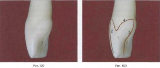
W. Downs (1948) was the first author of a cephalometric analysis of the skull in a lateral projection. According to W. Downs, an indicator that indirectly characterizes the height of the bite is the angle between the Frankfurt horizontal (FH) and the mandibular plane (Menton-Gonion), measured at 3 points (Orbitale, Porion and Menton) [13] (Fig. 1). Normally, this angle is 21.9±3.2°.
Rice. 1. Frankfurt horizontal plane FH is drawn between points Po - the upper edge of the bony auditory canal - and Or - the lower edge of the orbit, the mandibular plane (Menton-Gonion) is drawn between points Me - the lowest point of the mental symphysis - and Go - a point on the outer edge of the angle of the MF when it intersects with the bisector of the angle formed by the tangents to the lower edge of the body and the rear edge of the branch.
You cannot directly set the position of the LF by changing the angle of inclination of the mandibular plane and using the point of its intersection with the Frankfurt horizontal line as the axis of rotation. In this case, the head of the LF will significantly lower or rise inside the articular fossa, which is unacceptable from a clinical point of view.
A more correct approach and appropriate control of changes in the angle of inclination of the mandibular plane would be to rotate the MF around the hinge axis.
The average position of the LF hinge axis—point Ax (1, 2)—is determined according to the recommendations of R. Slavicek:
— build the hinge-infraorbital axis, which differs by 6.5° from the FH and passes through the condylar process of the MF;
— on the resulting segment of the intersection of the condyle with the hinge-infraorbital axis, mark point Ax (1, 2) in front of the posterior edge of the condyle contour at a distance of 2/3 of the length of this segment (Fig. 2).
Rice. 2. Determination of the average hinge axis (axis of rotation LF - point Ax (1,2)) according to Slavicek.
Our proposed method for determining the bite height using the TRG of the skull in the lateral projection, taking into account the Downs analysis, was as follows:
— the initial value of the angle of inclination of the NP was measured on a radiograph of the head in a lateral projection between the Or-Po and Me-Go axes;
— draw a line Me'—Go', parallel to Me—Go, through the rotation point of the NP Ax (1, 2) (Fig. 3);
Rice. 3. The line Me'—Go', drawn through the rotation point of the LF Ax (1, 2), is parallel to the line Me—Go.
— calculated the difference between the obtained value of the LF inclination angle and its normal value (
21.9º); the resulting difference can be positive or negative and is expressed in the angular value X (line Me2-Go2);
— then the LF contour was rotated around point Ax (1, 2) clockwise if the angle X is positive and counterclockwise if the angle X is negative; Thus, the angle of inclination of the LF corresponded, according to Downs, to the normal value, and the height of the bite was reduced to the normal value (see Fig. 3).
Determination of bite height based on TRG analysis of the skull in the lateral projection according to Steiner
In 1953, C. Steiner proposed a method for analyzing TRG of the skull in a lateral projection. This method is still one of the most popular all over the world, since the C. Steiner analysis is a balanced and comprehensive system for deciphering TRG of the skull in the lateral projection for skeletal, dentofacial and soft tissue formations, which can be used to predict the growth of the studied areas.
The skeletal component of the analysis allows us to determine the position of the HF and LF, as well as their position in relation to the skull and to each other.
C. Steiner's analysis uses the anterior cranial base or Sella-Nasion axis as the starting line for the skeletal region (Fig. 4). The Sella (S) and Nasion (Na) points are selected in such a way that they are located in the midline structures of the skull and do not depend on the possible rotation of the patient’s head in relation to the cephalostat.
Rice. 4. Na (nasion osseum) - point at the intersection of the median plane with the nasofrontal suture; the most anterior point of the sutura naso-frontalis; S (sella) - sella turcica (the geometric center of the fossa, determined visually); Go (gonion) - a point on the outer edge of the LF angle when it intersects with the bisector of the angle formed by the tangents to the lower edge of the body and the posterior edge of the branch; Gn (Gnathion) is the most anteroinferior point of the mental protuberance.
To measure the LF tilt angle, the angle between the Go-GN and S-N axes is used (see Fig. 4), which was proposed by Wylie and Johnson.
The angle of inclination of the LF, according to C. Steiner, is normally 32±4°.
Our proposed method for determining the height of the bite using the TRG of the skull in the lateral projection, taking into account the analysis according to C. Steiner, is as follows:
— the initial value of the angle of inclination of the LF was measured on a radiograph of the skull in a lateral projection (see Fig. 4);
— draw a line Go'—Gn', parallel to Go—Gn, through the average hinge axis of the NP Ax (1, 2) (Fig. 5);
Rice. 5. The line Go'—Gn', drawn through the averaged hinge spine of the NP Ax (1, 2), is parallel to Go—Gn; rotation of the LF contour around the point Ax (1, 2) until Go'—Gn' and Go2—Gn2 are aligned with each other.
— the difference between the obtained and normal values of the LF inclination angle was calculated, the resulting difference can be positive or negative and is expressed in the angular value X between the Go'-Gn' and Go2-Gn2 axes;
— then the LF contour was rotated around the point Ax (1,2) until the Go'-Gn' and Go2-Gn2 axes aligned with each other; thus, the angle of inclination of the LF was brought to a normal value, and the height of the bite corresponded to the normal value according to Steiner (see Fig. 5).
Determination of bite height based on Ricketts analysis
In 1956, R. Ricketts presented his method of cephalometric analysis, the main goal of which was to combine aesthetic and functional parameters and determine the direction of growth of the facial skeleton. The height of the lower part of the face was determined as the angle formed by the intersection of two axes: ANS—Xi and Xi—Pog (Fig. 6). According to R. Ricketts (1956), normally the angle ANS - Xi - Pog is 45°. Point Xi is determined by the intersection of the diagonals of a rectangle (R1, R2, R3, R4) parallel to the pterygoid vertical [PtV] (perpendicular to FH, passing along the posterior edge of the pterygopalatine fossa) (Fig. 7).
Rice. 6. ANS (Sna - spina nasalis anterior) - apex of the anterior nasal spine; Pg (Pog - pogonion osseum) - the most anterior point of the chin protrusion in the median section when the head is oriented along the Frankfurt horizontal; Xi is the geometric center of the LF branch proposed by Ricketts.
Rice. 7. R1 - point at the intersection of the deepest part of the anterior border of the LF branch and the perpendicular to FH; R2 is the point at the intersection of the middle part of the posterior border of the LF branch and the perpendicular to FH; R3 - point located on the lowest part of the sigmoid notch of the LF branch; R4 is the point at the intersection of the lower boundary of the LF and the perpendicular to FH passing through the point R3.
Our proposed method for determining the bite height using the TRG of the skull in the lateral projection, taking into account the Ricketts analysis, was as follows:
— measured the value of the actual angle ANS—Xi—Pog;
— on the TRG of the skull in the lateral projection, a new angle ANS-Xi-Pog' equal to 45° was laid out;
— then the LF contour was rotated around the Ax point (1, 2) until the Pog point intersected with the Xi-Pog' axis, which brought the bite height to the normal value according to Ricketts (Fig. 8).
Rice. 8. Angle ANS-Xi-Pog' is 45°; rotation of the LF contour around point Ax (1, 2) until point Pog intersects with the Xi-Pog' axis.
Determination of bite height based on McNamara analysis.
The cephalometric analysis of J. McNamara (1984) follows from the work of R. Ricketts and Harvold et al. This analysis includes a series of linear relationships of the HF dentition, maxillary bones, skull base and chin position.
According to McNamara, lower facial height is related to midfacial length. The height of the lower part of the face is measured from the ANS point to the Me point, the midfacial length is measured from the Co point to the A point (Fig. 9).
Rice. 9. ANS (spina nasalis anterior) - apex of the anterior nasal spine; Me (menton) - the lowest point of the mental symphysis; Co (condylion) - a point at the top of the contour of the articular heads; A is the deepest point of the anterior contour of the HF between the ANS and the incisor.
An increase or decrease in the size of the jaws is proportionally reflected in the height of the bite (see table).
The ratio of the length of the upper jaw (Co - A), the length of the lower jaw (Co-Gn) and the height of the lower part of the face (ANS-ME)
Our proposed method for determining the height of the bite using the TRG of the skull in the lateral projection, taking into account the analysis according to J. McNamara, was as follows:
— measured the initial midfacial length;
- using the table, according to the obtained value of the mid-facial length, the corresponding height of the lower part of the face was found;
— to visualize the trajectory of the NP movement, a circle was constructed with a center at point Ax (1, 2) and radius Ax (1, 2) - Me; then on this circle the position of the point Me' was noted, provided that the distance ANS - Me' corresponded to the value of the height of the lower part of the face found from the table;
— then the contour of the lower jaw was shifted around the rotation point of the LF Ax (1, 2) until the point Me intersected with the point Me', which brought the bite height to the normal value according to J. McNamara (Fig. 10).
Rice. 10. Displacement of the LF contour around its rotation point Ax (1, 2).
Determination of bite height based on analysis according to R. Slavicek
R. Slavicek (1989) presented his own method of cephalometric analysis, based on measuring angular values and taking into account the phenotypic variability of the patient.
This technique also uses the Xi point (the geometric center of the LF branch), however, unlike the Ricketts technique, the location of the Xi point is determined somewhat differently:
— first, a perpendicular to the FH plane is constructed through point R3 (the point located in the lowest part of the sigmoid notch of the LF branch);
— at the intersection of this perpendicular with the lower contour of the LF, point R4 is marked;
— then, parallel to the R3-R4 axis, a line is drawn through point R1 (the point of contact with the boundary of the notch on the front branch of the LF);
— a line parallel to the FH plane is drawn through point R1; at its intersection with the posterior border of the LF branch, point R2 is marked;
— then a line is drawn parallel to the R3-R4 axis through point R2;
— through points R3 and R4, lines parallel to the FH plane are constructed.
Lines constructed through points R1, R2, R3, R4 form a rectangle adjacent to the LF branch.
Point Xi is located in the center of the rectangle at the intersection of the diagonals (Fig. 11).
Rice. 11. Point Xi is the intersection point of the diagonals of the rectangle R1R2R3R4.
According to the analysis of TRG according to R. Slavicek, the height of the lower part of the face is determined by
glob formed by the intersection of 2 axes: Xi—ANS and Xi—Pm (Fig. 12).
Rice.
12. ANS (spinanasalis anterior) - apex of the anterior nasal spine; Pm (protuberantiamenti—suprapogonion) is a point on the bend of the anterior contour of the mental symphysis. The norm value is calculated using the formula:
58.0+0.2·(A)—0.2·(B)=Ideal vertical position (IVP),
where A is the angle of the mandibular plane (see Fig. 1), B is the angle of the facial axis (Fig. 13).
Rice. 13. Angle of the facial axis - the angle between the Nasion - Basion plane and the Pterygoid - Gnathion axis; Na (nasion) - the most anterior point of the frontonasal suture in the sagittal plane; Ba (basion) - a point in the middle of the anterior edge of the foramen magnum; Gn (gnathion) - a point located in the middle between the anterior and lower points of the bony part of the chin; PT (pterygoid) is a point at the intersection of the internal border of the round foramen with the posterior wall of the pterygomaxillary fissure.
Our proposed method for determining the height of the bite using the TRG of the skull in the lateral projection, taking into account the analysis according to Slavicek, was as follows:
— measured the values of the angle ANS—Xi—Pm, the angle of the mandibular plane and the angle of the facial axis (Ba—PT—Gn);
- then the ideal height of the lower face (IVP) was calculated using the given formula;
— on the TRG of the skull in the lateral projection, a new angle ANS—Xi—Pm' was plotted, the value of which was obtained from the IVP calculation data;
— then the contour of the LF was shifted around the point of its rotation of the LF Ax (1, 2) until the point Pm intersected with Pm', which brought the bite height to the normal value according to Slavicek (Fig. 14).
Rice. 14. Displacement of the LF contour around its rotation point Ax (1, 2) until the intersection of the point Pm with Pm'.
Analysis of TRG of the head in the lateral projection according to Seraidarian-Tavano
This technique was proposed in 2010 by Karine T. Tavano et al. and was developed on a group of patients with skeletal class I and the presence of all teeth, with the exception of third molars, as well as the absence of a history of orthognathic, surgical, orthodontic, reconstructive operations or restorative procedures on more than two molars in 1 quadrant.
For calculations using this method, the Frankfurt horizontal line, as well as the following points, were used as starting points:
—Na ( nasion osseum
) - point at the intersection of the median plane with the nasofrontal suture;
the most anterior point of the sutura naso-frontalis
;
— ENA ( anterior nasal bone
) - the most anterior point at the bottom of the nasal cavity, in the midsagittal plane;
point ENA is equivalent to point ANS (Sna - spina nasalis anterior
) (see Fig. 6, 8, 9, 10, 13, 14); in the further description we left the mention of ENA, as this is done by the authors Seraidarian-Tavano;
-Me ( menton)
) - the lowest point of the mental symphysis.
Our proposed method for determining the bite height using the TRG of the skull in the lateral projection, taking into account the Seraidarian-Tavano analysis, was as follows:
— the mandibular plane was marked (a straight line drawn through Me and the lowest point on the contour of the mandible in the area of the gonial angle);
— draw a tangent line to the posterior contour of the MF branch in the area of the most distal point of the condylar process of the MF and the ascending part of the gonial angle;
— at the intersection of these lines, a Go point was built;
— noted FH;
— marked the center of the face (point CF) at the intersection of the perpendicular to FH with the distal surface of the contour of the pterygopalatine fissure;
— built the CF-NA and CF-ENA axes;
— measured the angle of the upper third of the face Upper Angle (UA) (between the axes CF-Na and CF-ENA) (Fig. 15);
Rice. 15. Upper Angle (UA) - the angle of the upper third of the face between the CF-Na and CF-ENA axes; ENA (anteriornasalbone) is the most anterior point at the bottom of the nasal cavity, in the midsagittal plane.
— on the mandibular plane, an angle TLA was laid equal to the angle UA, with the apex at point Go and the zero line coinciding with the Me-Go line (Fig. 16);
Rice. 16. Angle TLA is equal to angle UA with its vertex at point Go and the zero line coinciding with the Me-Go line.
— at the intersection of one of the rays of the TLA angle with the CF-ENA axis, the 3rd angle MA is formed;
- according to the authors, normally the CF-ENA and Me-Go axes are parallel, and the angles MA and UA have the same values;
— then, through the rotation point of the jaw Ax (1, 2), lines CF'—ENA' and Me'—Goc' were built, parallel to the axes CF—ENA and Me—Go;
— moved the LF contour relative to the rotation point Ax (1, 2) together with the Me'-Go' line until the CF'-ENA' and Me'-Go' lines coincided, which brought the bite height to the normal value according to Seraidarian —Tavano (Fig. 17).
Rice. 17. Moving the LF contour relative to the rotation point Ax (1, 2) together with the line Me'—Go' until the lines CF'—ENA' and Me'—Go' coincide.
The proposed methods for determining the height of the bite according to TRG data provide the possibility of additional control of the correct determination of the height of the bite during the reconstruction of the dentition. Of interest is the probability of coincidence of the bite height determined by calculation methods of TRG using the methods of different authors - which of the described methods is the most accurate and suitable for use in the clinic or in automatic computer systems for constructing dentition?
We expect to find answers to the questions posed by further studying this topic.
How is teleradiography done?
The procedure is performed using a digital orthopantomograph. First, the patient removes all metal objects and jewelry and puts on a protective apron. Then the head is fixed in the desired position. The patient remains motionless.
The specialist turns on the device and the examination begins. At the end of the procedure, the finished image is displayed on the computer screen. This examination does not require any special preparation.
TRH is not recommended for pregnant women, children under 6 years of age, debilitated patients and patients receiving radiation therapy.
Contraindications
There are no specific contraindications to teleradiography. They are the same as contraindications to conventional x-ray examination. The procedure is not performed in the presence of bleeding and/or pneumothorax. It is also not given to patients in general serious condition (after accidents, injuries, in states of shock, etc.).
Can it be done by pregnant women?
Not recommended. This procedure is especially not recommended in the first and third trimesters, when the effects of radiation can negatively affect the child.
Teleradiogram before dental prosthetics
Photo interpretation
After receiving the finished image, the doctor interprets it. To do this, he needs to find and mark several points on the picture.
The main points are bone and soft tissue.
By drawing straight lines between certain points and calculating the angles between these straight lines, you can obtain data on the position of the jaws and the relationship of the teeth. You can also determine the bite, the type of pathology, or identify an abnormality in the development of the jaws.
Calculations help make a diagnosis and choose an adequate treatment method that suits a particular patient. A huge advantage of TRG is individualization. The angle values have normal limits, but in each specific case the values are calculated individually. This image also allows you to see the teeth in occlusion, this is important for correctly determining the bite. This method is not an intraoral examination and is therefore very well tolerated by all patients. Also, the resulting image fully corresponds to the actual dimensions of the anatomical structures of the patient’s skull, so we can talk about the accuracy of the calculations obtained by the doctor.
The TRG technique in orthodontics appeared not so long ago, but today this examination is often mandatory. Digital orthopantomographs provide high-definition images and the lowest radiation dose.
Using modern diagnostic methods, it is possible to significantly reduce the time of diagnosis and begin appropriate treatment as quickly as possible. Also, high-quality diagnostics makes it possible to prevent the occurrence of complications not only during, but also after treatment, as well as to identify hidden pathologies, if any. Modern comprehensive diagnostics is the key to the patient’s health.
Equipment used
When performing teleradiography, a special X-ray complex called an orthopantomograph is used, which consists of an emitter rotating around a person’s head and a digital sensor or film cassette.
Dental clinics most often use digital orthopantomographs, in which an image is formed on a matrix using X-rays and then transferred to a computer.
To ensure an accurate position of the patient's head, the orthopantomograph must be equipped with a cephalostat - a device that allows you to take a frontal profile image of the patient's jaw.