Parallelometry is a science that consists of studying and determining the parallelism of the axes of supporting teeth; it is used in orthopedic dentistry during the development and manufacture of high-quality dentures.
In the case when the prosthetic structure includes several clasps that perform a support-retaining function, it is necessary to determine the correct position of their shoulders in the supporting and retention points of the teeth.
This work is performed so that when fixing the denture, as well as when positioning it in the mouth, the support clasps do not loosen the teeth of the support points and distribute the pressure during chewing food strictly over all teeth of the denture.
Dental parallelometers
A dental laboratory uses equipment for cutting, grinding, sintering and fixing dentures, but without measuring instruments it is impossible to produce high-quality and comfortable dentures of the correct shape. A parallelometer is a device designed to determine undercuts and parallelism of the walls of abutment teeth, as well as to draw a survey line.
The device allows you to create artificial parallelism of teeth, choose the optimal direction for inserting the prosthesis and ensure reliable fixation of the clasps.
Parallelometry
In all cases, when several support-retaining clasps are included in the design of the prosthesis, it is necessary to find the correct location of their shoulders in the retention and support points of the teeth, so that when fixing the prosthesis, as well as during its removal from the oral cavity, the clasps do not loosen the supporting teeth, transfer chewing pressure strictly along their axis and rationally distributed it between the remaining teeth and alveolar processes.
The parallelometer was first used in dentures in 1918 by Fortinati. The parallelometer was subsequently improved by Ney, 1949; Nowak, 1955; Devin, 1956; V. Yu. Kurlyandsky et al., 1960, etc.
In our country, a parallelometer produced by the Volgograd Dental Materials Plant has become widespread (Fig. 58).
If you place a plaster model on the hinged table of a parallelometer and secure it so that the vertical axis of the tooth under study is parallel to the search rod of the parallelometer, then the stylus of the rod will outline the most convex part of the tooth - its belt.
The belt on chewing teeth most often passes along the contact points on the contact sides, on the vestibular surface it descends closer to the neck of the tooth, and on the lingual surface it runs almost along the center of the tooth crown.
If you install the search rod so that it touches the tooth belt, then a niche (undercut) is formed between the parallelometer rod and the tooth crown below its belt (Fig. 59). When designing clasps, this niche is used as a retention surface of the tooth to place the retaining arms of the clasps in it. It should be remembered that the tooth belt is the boundary above which the occlusal pads and other fixed parts of the clasps are always located. The spring parts of the clasp are always located under the tooth belt.
Since there is usually no parallelism between the abutment teeth, instead of determining the belt of each individual tooth, a common belt line is determined for all abutment teeth. There are graphical and analytical methods for determining the overall belt line. A simpler and more accessible analytical method was developed by Ney in 1959.
After installing the plaster model on the parallelometer table, the retaining zones of the supporting teeth are studied, after which the model is brought to the search rod and, by randomly rotating the table on a hinge, its position is found at which the angle formed by the parallelometer search rod and the retention surface of all clasp teeth is not the same. This creates optimal conditions for the location of the holding arm of the clasp. In this position, the parallelometer table is fixed with a screw, after which the search rod is replaced with a graphite stick, which is used to outline the belt line on the supporting teeth (also called a guide line, sight line, boundary line). The direction of the search rod to the general line of the belt is called the “path of insertion of the prosthesis”, since when it is inserted perpendicular to the general line of the belt, it is easily applied to the supporting teeth.
After finding the general line of the belt, they begin to determine the areas of the tooth on which parts of the support-retaining clasp will be placed. Since it is impossible to visually determine the suitability of a particular retention surface of a tooth for the placement of the retaining arms of clasps, after drawing the general line of the belt using gauges (Fig. 60), the severity of the retention surface is measured on the tooth and only after that the design of the clasp is determined.
The parallelometer has three gauges: No. 1, No. 2 and No. 3 with diameters of 0.25 mm, 0.5 mm and 0.75 mm, respectively. Using gauges, the position of the ends of the retaining arm of the clasp is determined and marked with a colored pencil on the supporting teeth. When using cast massive clasps with minimal springing capacity on teeth with a pronounced belt, a parallelometer of caliber No. 1 is used, since the short retaining arms are so rigid that they cannot pass the belt. Calibers No. 2 and No. 3 are used when the tooth belt is not clearly defined and when using elongated clasp arms made of elastic material. To determine the point on the abutment tooth from which the clasp pattern will begin, instead of a search rod, take a gauge and bring it to the retention zone of the abutment tooth. By moving it vertically, find a position where the gauge and the rod on which it is attached simultaneously touch the tooth (Fig. 61). From this point they begin drawing the springy part of the clasp arm.
Based on the fact that the parts of the clasp are located in relation to the tooth girdle in a strictly defined manner, from the point marked on the tooth with a pencil, a clasp pattern is applied so that only 1/4 of its shoulder is located below the tooth girdle. Otherwise, it is located on the tooth as shown in Fig. 62. The arms of the clasp pass through the belt towards the occlusal pad, and then into the process. When the design of the clasps is applied to the supporting teeth, the arches and other parts of the chosen design of the one-piece prosthesis are drawn out with a pencil. After this, the retention areas on the model, where clasps are not placed, as well as areas of the teeth facing the defect in the dentition, are filled with wax. Using a parallelometer knife, carefully, without damaging the model, cut off excess wax below the common belt line and create parallelism between the supporting teeth.
Then they begin to prepare the plaster model, duplicating it, making a fire-resistant model and modeling the components of the prosthetic splint in wax and casting the metal frame.
What does the device look like?
Modern equipment for measuring parallelism is installed on dental milling machines, which significantly increases the quality and accuracy of milling work. The cost of the device depends on the manufacturing company, ergonomics, functional equipment, and year of manufacture.
The device consists of a stand with a movable bracket, on which instruments for measuring dentures and cutting wax are mounted, and a flat working surface. There are several configuration options: with a movable clamp, a movable table, a fixed stand connected to the frame.
For convenient work with models, a replaceable set of rods is provided. The following types of rods are distinguished:
- to determine the survey line;
- for measuring work;
- for drawing survey lines;
- blades for cutting off excess wax.
The device body is assembled from aluminum parts. This approach allows us to achieve the necessary margin of strength and wear resistance, while ensuring low weight. Polymer spray coating provides electrostatic protection.
Studying jaw models in a parallelometer
The parallelometer necessarily includes a vertical rod, which is attached perpendicular to the horizontal platform (Fig. 6-1). The rod can move horizontally, as well as up and down. A special table is attached to the horizontal platform, on which the model being studied is installed. The parallelometer table can be positioned in different ways.
The vertical rod is the axis of the movement trajectory of the removable prosthesis, along which it is applied and removed from the cavity of the prosthesis - by introducing the prosthesis. This path can be changed by tilting the model mounted on the parallelometer table. By placing said vertical rod next to the teeth and area
Rice. 6-1. Dental parallelometer. A vertical rod (B) giving direction to the insertion path of the prosthesis, which can be selected by changing the inclination of the model mounted on the adjustable parallelometer table (C).
* This is not entirely accurate, since “parallelometry” is the study of the parallelism of the longitudinal axes of supporting teeth or their vertical (contact and oral) surfaces. — Note. ed.
| Partial dentures |
| Studying jaw models in a parallelometer |
Rice. 6-2. Tools for the parallelometer (from left to right): analyzing rod, measuring rods with undercut depth indicators 0.25; 0.5 and 0.75 mm, graphite rod, spatula for modeling wax blanks.
soft tissues displayed on the model, their morphology can be studied in relation to various ways of introducing the prosthesis. The various parallelometer tools are shown in Figure 6-2.
For any given route of insertion of the prosthesis, the contour line formed by connecting the points outlined on the most protruding areas of the teeth or soft tissues is called the “dividing (boundary) line.” The areas located below the dividing line for a given route of administration are called undercuts.
By positioning the graphite rod against the teeth and soft tissue, a dividing line can be drawn, running either low or high for each undercut area. These lines are ultimately combined into a single one, which completely outlines the undercut area.
| Rice. 6-3, Upper and lower dividing lines indicating the area of undercut on the buccal surface of the molar. |
Rice. 6-4. Different positions of the natural equator of the tooth (red)
and the dividing line for the chosen route of administration
(black).
Rice. 6-5. Factors influencing the choice of prosthesis insertion route. Once selected, the design of the removable denture can be completed.
nia (Fig. 6-3). Any rigid part of a partial denture must be designed outside the undercut area and only flexible parts can fit into it. The only flexible part of the partial denture is the tip of the retaining arm of the clasp.
The dividing lines and their corresponding undercut areas exist in relation to a given insertion route. Changing the route of administration results in a change in the topography of the dividing line and the undercut zone (Fig. 6-4). The final design should ideally allow for a single defined route of administration, which is clearly established by consideration of the factors presented in the accompanying diagram (Figure 6-5). The final design of the prosthesis can only be completed after the route of insertion of the prosthesis has been selected. Often in practice it turns out that the route of insertion of the prosthesis is a compromise among conflicting factors.
Retention
All removable dentures tend to be shed from the tissues of the denture bed during function. This is especially noticeable under the influence of viscous food during chewing, and in the case of an upper jaw prosthesis, in addition, due to gravity. For any given partial denture, this mixing can occur in several directions. However, all partial dentures are considered to have a tensile
| Studying jaw models in a parallelometer |
| Partial dentures |
| DOG |
tendency to be shed along a trajectory perpendicular to the occlusal plane—the “path of natural mixing.”
If the partial denture is retained, then it provides resistance to natural movement. This can be achieved by making the axis of natural displacement by withdrawing the prosthesis and creating a corresponding undercut. And then the clasps or rigid parts of the prosthesis will prevent this in accordance with one of the following three methods:
• using clasps, using an insertion path at right angles to the occlusal plane, i.e. similar to the path of natural mixing (Fig. 6-6). In this case, retention is conditional, since it depends only on the effectiveness of the clasps. This approach requires the use of “open”* relationships between the saddle and the supporting tooth in a partial removable denture, replacing the included defect in the dentition in the lateral region;
• by choosing an insertion route that is not at right angles to the occlusal plane (Fig. 6-7). Using this approach, the rigid parts of the denture can be positioned in areas that become undercuts when naturally displaced. An example is a removable denture that replaces the end defect of the dentition, in which resistance to natural displacement is ensured by a saddle that fills the undercut. This usually results in a “closed” seat-tooth abutment relationship. Thus, it is reasonable to expect that rigid elements will provide greater resistance to natural movement than the flexible holding arm of a clasp. In practice, however, the success of this half-stroke depends to a very large extent on the use of effective guiding surfaces that limit and reinforce the chosen path of insertion (for guidance surfaces, see below);
• a combination of both of the above approaches. This is probably the most effective way to improve retention. A clear example is partial dentures that replace anterior teeth (Fig. 6-8). The path is specifically chosen to reduce the undercut on the vestibular slope of the alveolar process. This
Rice. 6-6. Retention through the use of clasps that fill the undercut corresponding to the path of natural mixing (NAM) of the prosthesis.
Rice. 6-7. By changing the path of insertion (PA), the rigid parts of the removable denture (in this case, the acrylic saddle) can occupy areas of the contact surfaces that are undercuts corresponding to the path of natural mixing (PNA).
* “Open” relationship means that there is no contact of the undercut on the mesial or distal surface of the abutment tooth with the saddle. A “closed” relationship is defined when the seat is in close contact with one of the specified surfaces of the abutment tooth. — Note. ed.
Rice. 6-8. The choice of the presented route of insertion (PI) makes it possible to place the rigid labial side of the base in areas that are undercuts for the path of natural mixing (NAM) of the prosthesis. Molar clasps are designed to fit into the undercut that is common to both PV and PES.
| Partial dentures |
| Studying jaw models in a parallelometer |
makes it possible to place a rigid lip of the base there. This area is an undercut for the natural displacement path. The clasps on the lateral teeth are designed in such a way that they fill the undercut when the planned route of insertion and the path of natural mixing coincide. Therefore, if there is a compelling reason to choose a route of insertion other than that of natural mixing, clasps should be designed to fit into the undercut associated with both routes. If there is no retentive undercut suitable for clasps and there is no other reason to change the route of insertion, then using the path of natural displacement as the route of insertion is perfectly acceptable. The chosen route of administration should not differ from the route of natural displacement.
Ideally, the undercuts for the clasps should be equally pronounced. That is, they should not be very deep on some supporting teeth and very shallow on others. But this is not always the case. Modifications to the route of administration to create equivalent undercuts are very limited. Rather than changing the route of insertion to enlarge one of the undercuts, it is better to enlarge the latter with a filling or an artificial crown. This is especially true for a situation where the holding arm of the clamp will not fit into it. The final design of the clasps is postponed until the above-mentioned adjustment of the retention undercuts has been carried out.
Guide surfaces (planes)
Guide planes are a series of surfaces mutually parallel to each other and to the path of insertion of the prosthesis. At the same time, they ensure unhindered insertion or movement along the selected path of insertion of removable dentures (Fig. 6-9). To ensure effectiveness, they must be at least 2-3 mm high. A limited route of administration and elimination theoretically has several advantages:
• improved clasp functions. It must always be remembered that undercuts exist only in conjunction with the chosen route of insertion and removal. If a removable denture can be moved along a different path, then there may be no undercuts corresponding to that path. The effectiveness of retenia may turn out to be illusory. The limited escape route therefore increases the predictability of the planned retention undercut. In the future, when against
Rice. 6-9. Guide surfaces (SG), parallel to the intended insertion, limit the possible ways of removing a partial removable denture.
the acting clasp arms or bases are in contact with the guide surfaces, their contact with the tooth is maintained if the removable denture begins to be ejected from the tissues of the prosthetic bed. Effective counteraction is ensured, and the flexible holding arm of the clasp should spring back when exiting the undercut. As a result, the limited insertion path prevents possible deformation of the flexible retaining arm of the clasp, which can occur with a different version of the application of a removable denture;
• ease of self-insertion and removal of a removable denture from the oral cavity by the patient;
• frictional contact of removable denture elements with guide surfaces can contribute to the overall retention of partial dentures;
• reduction of “dead” spaces. Working with dead spaces is described in more detail later in this chapter.
A good example of a bonding surface is a high-precision locking fastening. In order to ensure efficiency, parallel surfaces are prepared, embedded in a cast crown covering the abutment tooth, if significant restoration is necessary (Fig. 6-10). Guide surfaces can also be prepared by grinding the enamel surface of the supporting tooth, but the likelihood of this creating several tooth surfaces mutually parallel to each other and the path of insertion is minimal (see Chapter 10).
| Partial dentures |
| Studying jaw models in a parallelometer |
| Rice. 6-10.Guiding surfaces on the mesial and lingual surfaces of a maxillary molar covered with an artificial crown. A milled ledge begins from the lingual guide surface, on which the opposing arm of the clasp rests. |
unaesthetic clasps. In this regard, the tips of the clasp arms on the anterior teeth should be located as close as possible to the gingival margin or to the distal surfaces of the teeth (Fig. 6-11). Using the mesial undercut for an occlusally appropriate clasp will allow the proximal 2/3 of the arms to remain on the distal surface of the tooth, and bring the tip closer to the gingival margin. For a gingivally appropriate clasp, it is better to use a distally located undercut so that the clamp arm is less noticeable.
The elimination of unaesthetic gaps between artificial and abutment teeth, as well as the use of artificial gums when replacing anterior teeth, seriously limits the choice of route of insertion (Fig. 6-12). It is usually towards the rear for a forward tilt model.
Even in the absence of artificial crowns and preparation of tooth surfaces within the enamel, it is possible to detect some surfaces of the supporting teeth that will be parallel to each other. In this case, three parallel lines on the teeth, located at a large distance from each other, can be effective if they are in contact with the frame. Long parallel surfaces for a fitted frame can be effective guide planes. Although the tooth surfaces are not perfectly parallel and the denture can only contact the teeth along the outer line, they can enhance the stability of the insertion path.
Effective guiding surfaces are often reported to significantly reduce clasp retention in partial dentures. However, there is insufficient evidence to support the benefits of classical clasps for the long-term performance of partial dentures. Modern concepts in the design of partial removable dentures place much less emphasis on the need for guidance surfaces. In addition, the covering of intact abutment teeth with artificial crowns for the sole purpose of creating effective guiding surfaces is often frowned upon.
Aesthetics
The visibility of metal elements of removable partial dentures should be kept to a minimum. Although, on the other hand, sacrificing the stability of a removable denture seems unreasonable. The patient's unsatisfactory appearance may be associated with noticeable
Rice. 6-11. Aesthetic location of the clasp. suitable (a) occlusally and (b) gingivally.
/ lllll
• L"
Rice. 6-12. (a) The likelihood of a space appearing msial to the upper lateral Incisor when delineating its natural equator, (b) The use of an insertion route in posterior tilting with a slight lateral tilt reduced the indicated space and, in addition, made the use of artificial gum possible.
| Studying jaw models in a parallelometer |
Partial dentures
Dead spaces and interference
"Dead" spaces
Any unwanted area of undercut located below the boundary line on the surface of an abutment tooth, in the immediate vicinity of the partial denture framework, or on other teeth in contact with the framework is called dead space (Figure 6-13a). It represents areas where food debris can accumulate and be retained. Therefore, they should be kept to a minimum or left wide enough for the purpose of natural cleansing. There are several ways to deal with dead spaces:
• elimination of “dead” spaces by grinding away the hard tissues of the tooth (see Fig. 6-9). This can be achieved by preparing the guide surfaces, which can often be done without removing the entire enamel layer. However, with a pronounced inclination of the supporting teeth, it is more rational to eliminate the “dead” space by covering the tooth with an artificial crown;
• by deliberately increasing the volume of “dead” spaces when constructing partial removable dentures (Fig. 6-136). This method results in a “hygienic” open relationship between the saddle and the abutment tooth and is usually used on saddles resting on the lateral teeth. In this case, retention associated with the path of natural shedding must be ensured with the help of clasp arms filling the undercut corresponding to the specified path of mixing of the prosthesis;
• by choosing a route of administration that eliminates unwanted areas of undercut (Fig. 6-13c). This method has the additional advantage of eliminating unsightly gaps between abutment and artificial teeth, especially when replacing anterior teeth. This also has a functional advantage. It consists of resistance due to the introduction of rigid elements of the prosthesis into the undercuts corresponding to the path of its displacement. The presence of included defects in the dentition in the lateral region often leads to an increase in “dead” space in front of the mesial surface of the distal abutment tooth.
Although food accumulation may cause discomfort to the patient, the effect of either eliminating dead spaces (closed saddle-to-abutment relationship) or increasing them (open saddle-to-abutment relationship) has not been fully proven. Although su-
Rice. 6-13. “Dead” spaces between the saddle and the abutment tooth (a). Eliminated by deliberate expansion (b) and choice of route of administration (RO). which eliminates unwanted dead spaces located at the distal surface of the mesial abutment tooth (c).
| Partial dentures |
Rice. 6-14. Examples of interference: (a) lingually inclined premolar; (b) mandibular ridge.
Although there are functional and aesthetic benefits associated with reducing dead spaces, the decision to exclude them as such is not always fair. Sometimes careful removal of plaque is more important for the effectiveness of partial dentures in the long term of their use.
Interference
Teeth and soft tissue may be shaped or positioned in such a way that they physically interfere with the placement of the rigid elements of the denture according to the optimal route of insertion (Figure 6-14). Therefore, they can be considered as obstacles or hindrances. Probably the most common interferences are lingually inclined premolars and carvings. Other examples include the mandibular ridge, which prevents the use of the lingual arch, and the bony projections of the edentulous alveolar ridge, which prevent the creation of normal denture seat area.
An administration route that bypasses the obstruction may result in undesirable distribution of retention undercuts and alteration of the patient's appearance. In such a case, obstacles should be eliminated by providing a route of insertion that will enhance the functional qualities of the prosthesis.
Design of arches and branches of partial dentures
relevant to the specific clinical picture. Parallelometry is an integral part of the design process. It allows you to determine the appropriate insertion route for optimal esthetics and retention of the partial denture. Unfortunately, the vast majority of doctors shift this responsibility to dental technicians, citing reasons such as lack of time, trust or skill. The author is of the firm opinion that the design of partial dentures, including parallelometry, is the responsibility of the clinician*.
The dental technician may simply not have the clinical information necessary to select a partial denture design for a particular patient. To facilitate this clinical responsibility, Chapter 9 provides a simple and logical system for creating effective and appropriate partial denture designs that can be easily followed by the clinician (“Clinical Guide II: Selecting a Denture Design”).
Key points
• Parallelometry of the model is an integral element of the partial denture design process, which allows the appropriate route of insertion to be established.
• The route of administration is determined according to the requirements of retention and esthetics and, to a lesser extent, guiding surfaces, dead spaces and interference.
• Once the route of insertion has been selected, the construction of the removable denture can be completed.
• The design of removable partial dentures is the responsibility of the physician and should not be left to the dental technician.
Parallelometry in practice
for ?obtYao3o!GSTIVRACH^ INCLUDE the creation of a partial removable denture, which must not only be effective, but also appropriate-
* The editor fully supports this point of view. Firstly, only the doctor plans treatment. Secondly, the doctor is primarily responsible for the quality of the prosthesis.
| Temporary partial dentures |
Chapter 7
Where to buy an inexpensive parallelometer
Finding a cheap dental device is not an easy task. Dental equipment is expensive, as it belongs to the category of complex equipment. If you do not want to overpay, we recommend purchasing a working used device. You can find suitable equipment for a dental laboratory on the pages of the BiMedis service, a leading online platform for the purchase and sale of medical equipment.
BiMedis has brought together sellers and buyers from all over the world. Anyone can post a sale advertisement: both legal entities and individuals. To choose the option that best suits your budget, use a special filter. The system allows you to sort search results by the following criteria: price, year of manufacture, product location, type (new, used, refurbished), device model. It is possible to exchange personal messages to agree on the details of the transaction.
If you want to sell medical equipment, post your own ad! The feature is provided free of charge.
How are jaw models made?
The study of a jaw model begins with its manufacture. The model is cast from high-quality durable plaster, after which it is dried and carefully trimmed (combed) on all sides.
The finished base of the jaw should not be less than 1.5 cm. The walls located on the sides of the model must be parallel to each other, as well as perpendicular to the base of the jaw.
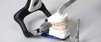
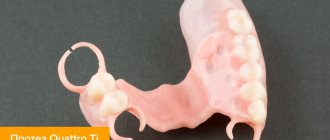
Manufacturing of clasp dentures, one of the stages of which is parallelometry: